
Kinematics of 5-Axis Milling
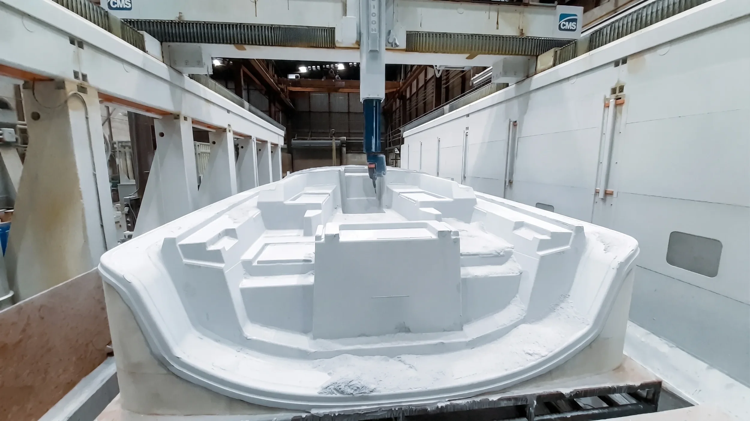
In large-scale maritime tooling, the transition from a digital surface to a physical plug is where the greatest risk of volumetric error occurs. When milling a 15-meter hull plug, the primary challenge is not the speed of the spindle, but the management of kinematic stability and material behavior over long machining cycles. At RnD, we treat 5-axis milling as a high-precision metrology task, focusing on three critical variables: tool deflection, thermal drift of the substrate, and coordinate system alignment.
Managing Tool Deflection and Reach
Large-scale maritime plugs require significant tool extensions to reach deep into hull or keel sections. As the distance between the spindle and the cutting edge increases, so does the risk of tool deflection and vibration (chatter).
To mitigate this, our CAM strategies utilize variable-axis pathing to keep the spindle as close to the surface as possible while maintaining the optimal angle of attack. We prioritize constant chip-load toolpaths, which ensure that cutting forces remain uniform across varying material engagement. This minimizes deflection-induced surface irregularities (e.g., chatter marks or waviness) that would otherwise require extensive manual post-processing.
Note:
Scallop height is primarily determined by stepover and tool geometry. Our approach controls deflection to prevent additional surface artifacts beyond the nominal scallop.
Thermal Stability of the Substrate
Even with high-density modeling boards (PUR or epoxy), large plugs are susceptible to thermal expansion and contraction during a 48-hour milling cycle. A temperature shift of just 5°C in the workshop can produce a measurable deviation, on the order of 1.5–4 mm over 10 meters, depending on the material’s coefficient of thermal expansion (CTE).
Environmental control: Our milling environment is temperature-stabilized to ensure that the substrate remains dimensionally constant throughout the cycle.
Roughing and finishing strategy: We never move directly from a roughing pass to a finishing pass. After bulk material removal, we pause to allow the substrate to thermally equalize, dissipating the frictional heat generated during cutting and stabilizing any localized temperature gradients, before executing final finishing paths.
Spindle thermal monitoring: In long-duration runs, spindle bearing heat can also cause Z-axis drift. We monitor spindle temperature and apply real-time compensation where available.
Coordinate System Integrity
For massive structures that exceed the bridge travel of a single CNC machine, or require repositioning, maintaining the integrity of the global coordinate system is paramount. We utilize laser trackers and physical reference markers (datums) bonded directly to the plug. This ensures that when the machine moves from bow to stern sections, the surfaces align within a verified tolerance (typically ±0.5 mm) , eliminating the “steps” or ridges often found in lower-tier tooling operations.
Practical Note: When to Expect Sub-Millimeter Results
Achieving sub-millimeter alignment after repositioning requires not only metrology but also machine stiffness, environmental stability, and proper datum design. Our process is validated on each project using post-machining 3D scanning; the quoted tolerance applies to plugs produced under controlled shop conditions (temperature ±2°C, humidity <50% RH).
By controlling these kinematic variables, RnD delivers plugs that are not just visual representations, but high-precision industrial masters. This precision at the plug stage is the only way to ensure that the production molds, and the resulting hulls, meet the hydrodynamic requirements set by the naval architect.