
Reducing Composite Tooling Risk
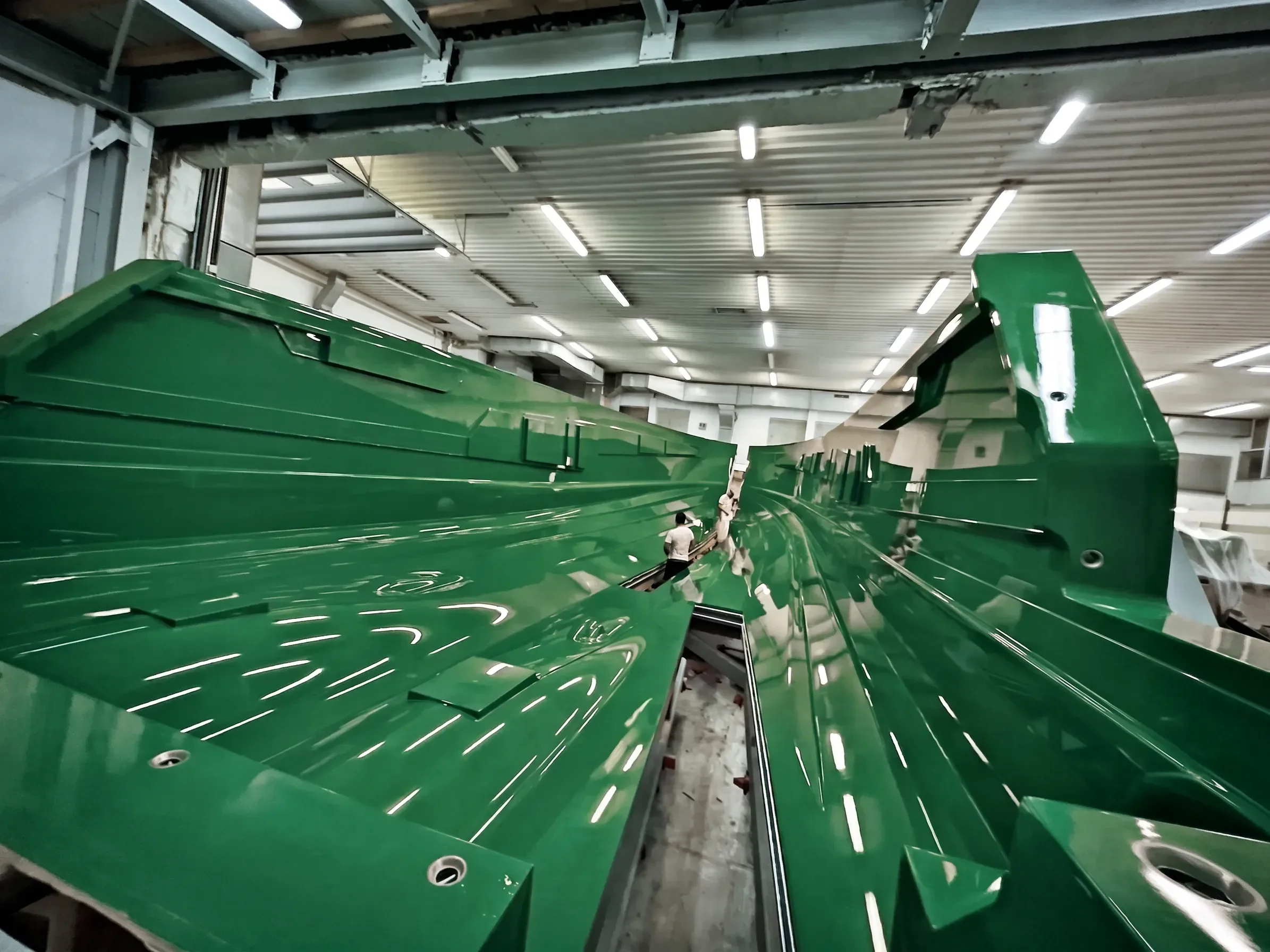
The traditional sequential workflow in yacht construction, moving from naval architecture to an independent tooling facility, introduces a high risk of geometric drift. In production boatbuilding, where tolerances are increasingly tight, the gap between a CAD surface and a physical mold can lead to assembly failures, poor part release, or rejected hulls. At RnD, we utilize a Concurrent Engineering (CE) framework in partnership with J&J Design to identify and neutralize these technical bottlenecks during the modeling phase, rather than on the shop floor.
Addressing the Physics of the Mold
A common failure in siloed workflows is the neglect of how composite materials behave during cure. Engineering a mold is not merely a subtractive task of milling a shape; it is a thermal management challenge.
Exothermic Heat Management: Thick laminate sections in the final part generate significant exothermic heat. If the mold design fails to account for this thermal energy, the resulting part may suffer from print-through (surface finish degradation) or structural warping. The mold must be designed with adequate thickness, strategic material selection, and, in high-rate scenarios, integrated cooling features to manage heat dissipation.
CTE Alignment: The Coefficient of Thermal Expansion (CTE) mismatch between the plug material (e.g., low-density modeling board), the tooling resin, and the final part is a major contributor to dimensional inaccuracy. This is particularly critical for elevated-temperature cures (above 80°C). By integrating tooling expertise into the design phase, we select resin systems, typically Vinyl Ester (VE) for room-temperature production or Epoxy for high-temperature prepreg applications, that align with the thermal profile of the specific geometry.
From “Zero-Loop” to Rapid Closed-Loop Validation
While the industry sometimes speaks of "seamless transitions," engineering reality dictates that complex freeform hull shapes always require iteration. The goal is not a “zero-loop” process (which is statistically improbable) but a rapid closed-loop transition.
During the design phase, we evaluate surfaces for cutter accessibility and tool deflection. Identifying a non-draftable surface, or a geometric feature that would require excessive manual finishing due to machining limitations, at week two of design prevents hundreds of hours of rework at week eight of production. This is particularly critical for high-volume production runs (>15 units), where the cost of a tooling error multiplies across the entire series.
Note:
Predictable results also require stable milling environments (temperature and humidity control) and high-density modeling boards suitable for the intended cure cycle. Even the best CE process cannot compensate for material instability or uncontrolled shop conditions.
As-Built Conformance via 3D Metrology
The term “Digital Twin” is often misapplied to static models. In professional tooling, we focus on As-Built Digital Validation. Upon completion of the milling process, we use 3D scanning metrology to verify the physical plug against the original CAD intent.
This as-built model serves as the baseline for the production mold. It ensures that any manual post-machining or hand-finishing required to reach a moldable surface does not compromise the underlying geometry. By quantifying the deviation between “as-designed” and “as-built,” we provide shipyards with a verified starting point for mass production, ensuring that the first hull off the line meets the naval architect’s performance specifications.
Practical Impact: A Case Study in Efficiency
On a recent 40-foot catamaran project, the early integration of tooling engineers allowed us to identify a structural bulkhead interface that lacked sufficient draft for the intended production rate. By adjusting the surface geometry before the first CNC path was generated, we eliminated an estimated 120 hours of manual mold modification compared to traditional sequential workflows on similar prior projects. In an industry where time-to-market is a competitive lever, this integration is not a luxury, it is a technical necessity.
When CE Makes Sense (and When It Doesn’t)
Concurrent engineering delivers maximum value for production runs above approximately 15 units. For one-off custom builds or prototypes, the overhead of aligning design and tooling teams may exceed the savings from avoided rework. We recommend a project-by-project assessment to ensure the engineering effort aligns with the production scale. •